
Tai dar vienas Princeton produktas skirtas VFD indikatoriams: PT6302. Pakėliau, nes ant PCB buvo sumontuotas ir VFD ekranas ir įtampos keitiklis.
Čia nieko specialaus, palyginus su kitais modeliais, čia nėra mygtukų kontrolerio (PCB turi atskirą reikalą mygtukams), todėl valdymui užtenka trijų laidelių: CLK, CS, DATA.
Deja, tai ne “grafinis” kontroleris, todėl turi tik aštuonis vartotojo programuojamus simbolius. Tačiau simbolius galima perprogramuoti “gyvai”, todėl galima ir šiokia tokia animacija.
O daugiau nieko.
Source code AVR megai ir kitkas:PT6302 source code for AVR ATMEGA16 .
Hello. can you post a’n example in Arduino IDE to controll this vfd?
I have one of this 1×16 vfd, but in Arduino IDE I cannot make it work.
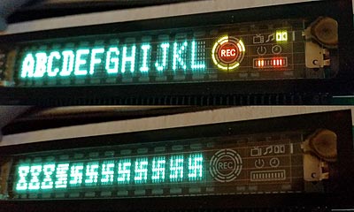
This is what I managed to do, the display is running, but the characters shown on the display are not what I want to print…
//Pin connected to CSB of PT6302
int latchPin = 4;
//Pin connected to CLK of PT6302
int clockPin = 2;
////Pin connected to DIN of PT6302
int dataPin = 3;
byte data;
byte dataArray[16];
void setup() {
pinMode(latchPin, OUTPUT);
pinMode(clockPin, OUTPUT);
pinMode(dataPin, OUTPUT);
dataArray[0] = 0b11111000; // initial data 08
Serial.begin(9600);
vfd_begin();
}
void loop() {
vfd_print(15, “2”);
delay(2000);
vfd_clear();}
void shiftOut(int myDataPin, int myClockPin, byte myDataOut) {
int i=0;
int pinState;
pinMode(myClockPin, OUTPUT);
pinMode(myDataPin, OUTPUT);
digitalWrite(myDataPin, 0);
digitalWrite(myClockPin, 0);
//for each bit in the byte myDataOut�
//NOTICE THAT WE ARE COUNTING DOWN in our for loop
//This means that %00000001 or “1” will go through such
//that it will be pin Q0 that lights.
for (i=7; i>=0; i–) {
digitalWrite(myClockPin, 0);
//if the value passed to myDataOut and a bitmask result
// true then… so if we are at i=6 and our value is
// %11010100 it would the code compares it to %01000000
// and proceeds to set pinState to 1.
if ( myDataOut & (1=0 ; i–){
shiftOut(dataPin, clockPin,0b00000000);} // switch off extra “ADRAM”
delay(10);
digitalWrite(latchPin, 1);
digitalWrite(latchPin, 0);
shiftOut(dataPin, clockPin,0b11001110); // test mode: light all
delay(10);
digitalWrite(latchPin, 1); delay(500);
digitalWrite(latchPin, 0);
shiftOut(dataPin, clockPin,0b00001110); //normal mode
delay(10);
digitalWrite(latchPin, 1);
}
void vfd_display(unsigned char address, unsigned char data)
{
switch (address){
case 0: dataArray[0] = 0b00001000; break;
case 1: dataArray[0] = 0b10001000; break;
case 2: dataArray[0] = 0b01001000; break;
case 3: dataArray[0] = 0b11001000; break;
case 4: dataArray[0] = 0b00101000; break;
case 5: dataArray[0] = 0b10101000; break;
case 6: dataArray[0] = 0b01101000; break;
case 7: dataArray[0] = 0b11101000; break;
case 8: dataArray[0] = 0b00011000; break;
case 9: dataArray[0] = 0b10011000; break;
case 10: dataArray[0] = 0b01011000; break;
case 11: dataArray[0] = 0b11011000; break;
case 12: dataArray[0] = 0b00111000; break;
case 13: dataArray[0] = 0b10111000; break;
case 14: dataArray[0] = 0b01111000; break;
case 15: dataArray[0] = 0b11111000; break;
}
digitalWrite(latchPin, 0);
shiftOut(dataPin, clockPin, dataArray[0]);
shiftOut(dataPin, clockPin, data);
delay(500);
digitalWrite(latchPin, 1);
}
void vfd_print(unsigned char address, char *text)
{
switch (address){
case 0: dataArray[0] = 0b00001000; break;
case 1: dataArray[0] = 0b10001000; break;
case 2: dataArray[0] = 0b01001000; break;
case 3: dataArray[0] = 0b11001000; break;
case 4: dataArray[0] = 0b00101000; break;
case 5: dataArray[0] = 0b10101000; break;
case 6: dataArray[0] = 0b01101000; break;
case 7: dataArray[0] = 0b11101000; break;
case 8: dataArray[0] = 0b00011000; break;
case 9: dataArray[0] = 0b10011000; break;
case 10: dataArray[0] = 0b01011000; break;
case 11: dataArray[0] = 0b11011000; break;
case 12: dataArray[0] = 0b00111000; break;
case 13: dataArray[0] = 0b10111000; break;
case 14: dataArray[0] = 0b01111000; break;
case 15: dataArray[0] = 0b11111000; break;
}
unsigned char c;
digitalWrite(latchPin, 0);
shiftOut(dataPin, clockPin, dataArray[0]);
while ( (c = *text++) )
{ shiftOut(dataPin, clockPin,c & 0b11111110); }
delay(500);
digitalWrite(latchPin, 1);
Serial.println(c & 0b11111110);
}
void vfd_clear(){
digitalWrite(latchPin, 0);
shiftOut(dataPin, clockPin,0b00001000);
for (int j = 15; j >= 0; j–) {
shiftOut(dataPin, clockPin,0b00000100);}
digitalWrite(latchPin, 1);
delay(10);
digitalWrite(latchPin, 0);
shiftOut(dataPin, clockPin,0b00001100);
for (int j = 15; j >= 0; j–) {
shiftOut(dataPin, clockPin,0b00000100);}
digitalWrite(latchPin, 1);
}
void vfd_uchar(unsigned char n, unsigned char *font)
{ unsigned char c;
digitalWrite(latchPin, 0);
shiftOut(dataPin, clockPin,0b00000100 + (n & 0b11100000));
delay(100);
while ( (c = *font++) )
{ shiftOut(dataPin, clockPin,c>>1 & 0b11111110); }
delay(100);
digitalWrite(latchPin, 0);
}
I do not use Arduino environment. It uses quite lame libraries.
And about characters… your VFD maybe wires/organized in different way and you need to design your own font.
Hello again !
I make it to work with your example but as you can see in the photo, the grids ar backwords from normal. 0 is in right and 15 in left.
How will you modify your code if you have this problem?
In my code text is printed using automatic address increment.
If your module is wired in reverse order: VABOLIS < -> SILOBAV, it is possible to send each character to proper video RAM space individually.
Like:
And do it for each character.
…
But if you use your code, there maybe some shit in this monster:
and the bit order in shifout procedure is mixed. (LSB and MSB order). This causes ALL the crap.
Second position is 0b10001000 in your procedure. In my procedure 0b00010001. Obviously, bit order is other.
Hello Stefan
Would you have some VFD codes for Arduino and could you share with the schematic? Thank you
@Stefan
I copied your sketch and it is showing the following: ‘vfd_begin’ was not declared in this scope
@Administrator
I would like to open and write this code in the Arduino IDE.
@Daniel Fernandes – I do not use any Arduino quasi language, so I can not help with specific commands or declarations. That vfd_begin may be the name of main program called after init. Every program does something useful and displays result- in this case on VFD. This part was omitted in this source code as it is uninteresting for VFD display problem.
I am programming in pure C and I am very happy that never used Arduino- now I am programming STM32 controllers without any problems, also, I can port my programs to any available device with gcc.
When you know pure C, you can even port ancient software (1987?) for some personal computer to modern MCU without big problems. Check Rogue port to STM32+USB.
@Administrator
Thank you and success in your programming!