Mano indukcinio kaitinimo aparatui reikia daug maitinimo šaltinių. Ir durniausia tai, kad reikia nepriklausomų šaltinių (float). Dabar naudoju standartinius 50Hz transformatoriukus, bet iškilo keletas problemų. Pirmiausia- standartiniai maži transformatoriukai turi vieną ar dvi išėjimo apvijas. Maži transformatoriukai labai negalingi- 5…7W. Tokios galios pilnai užtenka indikacijai ar pagrindinei plokštei. Tačiau IGBT draiveriams ir ventiliatoriui su vandens pompa tai jau per mažai. Pagalvojau pritaikyti maitblokį iš LCD monitoriaus. Viduje stovi Fairchild FSDM0565R mikroschema. Šį mikroschema teoriškai leidžia sukonstruoti 60 – 70W maitblokį. Man tiek vatų nereikės, bet rezervas nepamaišys.
Mano “aparatui” reikia šių įtampų:
- 12V stabilizuotos apie 1A IGBT draiveriams
- maždaug 12V prie 1…2A vandens pompai
- maždaug 12V prie 1…2A ventiliatoriams
- 5V stabilizuotos, 200mA (?) voltmetrui
- 5V stabilizuotos, 200mA (?) ampermetrui
- apie 15V prie 100 … 200mA pagrindinei plokštei
Kadangi visi išėjimai nepriklausomi (vandens pompa ir ventiliatorius galima užbendrinti) tai iškilo problemos su stabilizacija. Todėl nusprendžiau stabilizuoti tik IGBT draiverių maitinimo šaltinį. Ventiliatorius sėkmingai dirba ir prie 5V ir prie 15V. Voltmetras ir pagrindinė plokštė turės savo stabilizatorius (2 x 7805 ir 7812).
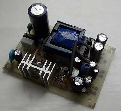
Gavosi va toks “šedevras”. Čia dar nesumontuoti du 7805. 7812 jau seniai stovi pagrindinėje plokštėje. Plokštės “laboratorinis” testas atliktas, veikia. Tik reikėtu nustatyti tiksliai 11..12V išėjimą. Trafuką pavyko suvynioti kokybiškai, tai kitos įtampos nelabai stipriai vaikšto apkrovus stabilizuojamą išėjimą.
Schema pagal gamintojo datasheetą, visos detalės išluptos iš LCD monitoriaus maitblokio. Tik teko pervynioti transformatorių. Tinklo apvija 40 vijų, 12V apviją apie 10 vijų.
Skylutes po transformatorium išgrežiojau kad geriau vėdintusi, bet čia neprivalomas reikalas.
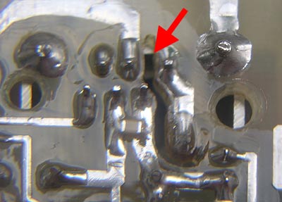
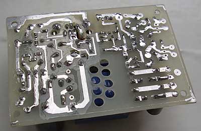
Tačiau šitą plyšį rekomenduoju išfrezuoti. Ir aukštos įtampos pusę geriau nulakuoti. Turėjau nutikimą, kad gerai veikianti impulsinio maitblokio plokštė po metų darbo susvilo vien tik dėl drėgmės ir dulkių.
Cadsoft Eagle schema ir PCB: RAR archyvas. (Ten dar yra biblioteka su mano detalėm)
Sureguliavau išėjimo įtampą. Nustačius draiverių įtampą lygiai 12V, ventiliatorių apvija su pilna apkrova (12V 1.5A turbina ir 24V 0.23A ventiliatorius) duodai apie 10V. Laisva identiška apvija duoda 15V.
Padariau vieną klaidą- 7812 čipui maitinančiam pagrindinę plokštę padariau tik 12V apviją. Teko privynioti apie 6 vijas KYNAR laidelio ant trafo viršaus. Dabar su apkrova 7812 maitinamas apie 19V. Kiek perdaug, nes čipukas šiltas.
Trafukas gavosi toks:
Tinklo apvija 40 vijų 0.28mm diametro laidas (visur naudojau tą patį storį, tik kituri ėjo po kelis laidus).
Draiveriai- 10 vijų, 4-gubas laidas.
Ventiliacija ir siurblys- po 10 viju dvigubo laido.
Indikacija (V ir A)- 10 vijų viengubo laido.
Pagrindinė plokštė- apie 16 vijų viengubo laido.
Fairčaild čipo maitinimas- 10 vijų viengubo laido.
Vyniojant trafą svarbu nesupainioti vyniojimo kryptis ir apvijų pradžias.
Grazus daiktas!
O kaip isardai originalius trafukus? merki i acetona?
Užtenka pašildyti su fenu ir klijai bei lakas suminkštėja.
bro, savelkaunas, i am ur fan from youtube. i couldnt open all the files from the RAR download files, only : eagle.BRD, psu01.PRO, and psu01.SCH.
the file psu01.SCH had the schematic but couldnt find the components name, bro. can u help giving hints about this, i used eagle 5.9 as freeware, man
All needed components are in library LevoROMS.lbr. Install it to library folder.
im sorry to say this, but i couldnt do that, new to this program, just installed it and knowing nothing to operate it thought it seemed easy, i think something went wrong with the installation, errors all the time when installing.
like most ofthe others induction heaters enthusiasts, i am new to electronics too, bro. so i need to gather the components first before beginning to understand the pcb working. would you help us, the amateurs of electronics to attach another .RAR file to download consisted of the list of the components in notepad file, and the pictures of the completepcb, se we can learn how the components linked together, how would it be if we made a success building one like yours. please, bro, we, the amateur enthusiasts, always get confused of how to do these cool stuffs you did, man
please help man, dont need to be super specific about the pics, just the pics u took when the pcb and the other complicated components like power supply, man
i am so sorry to say this man, but i have tried it for several hours once again and still couldnt make it, i think somehting was wrong with the installing, just couldnt view the components, but the pcb and schematic were ok to view.
most of us, eletronics diy enthusiasts, are newbies in electronics and dont know how the programs work and need pics for the instructions, we are always confused all times, when we have to dive into deepness of ur professional skills, bro.
man, would you help us, ur fans, to attach another .RAR file consisted of pics of completed setup; the complicated parts and what a complete setup look like, and a notepad file of components.
not all of us, newbies, can do it in eagle, bro, like me couldnt do it too, man
please help, bro, please save me from the frustrating condition
This is generic PSU using schematics from Fairchild semiconductors default datasheet. Nothing new. I don’t know if it is possible to build this PSU without knowledge of how it works and how to build transformer.
There are several articles in Lithuanian language:
http://www.vabolis.lt/2006/03/22/trafuko-vyniojimas/
http://www.vabolis.lt/2006/03/07/galingo-maitblokio-transformatorius/
http://www.vabolis.lt/2006/03/06/galingas-maitblokis-su-keliais-isejimais-2/
http://www.vabolis.lt/2006/03/05/galingas-maitblokis-su-keliais-isejimais/
Some of these articles are translated into English language:
http://blog.savel.org/2006/03/23/winding-the-transformer/
http://blog.savel.org/2006/03/08/transformer-for-psu/
http://blog.savel.org/2006/03/06/high-power-psu-2/
http://blog.savel.org/2006/03/05/high-power-psu/
And this PSU is not mandatory. It just make my life better and save lots of space in my induction heater box.
Component placement:
PCB image (600dpi).
Image of schematics:
Image for printing.
R10 – 4.7K, R11- 12K (as I remmember 🙂 )
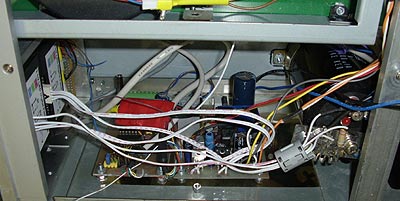
This new PSU replaced this:
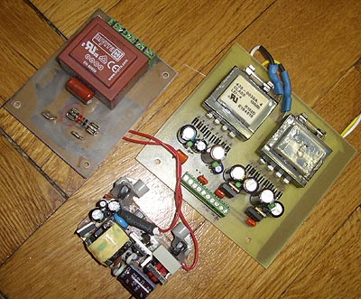
There are 3 transformers and one pulsed PSU.
Old PSU in the box:
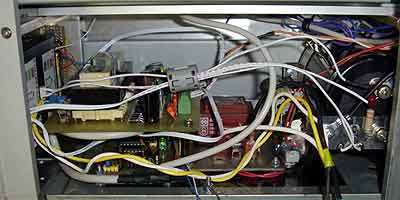
And now my heater’s electronics section looks like this:
New PSU, PLL generator, U coil detector (wrapped in RED). Heater is working BAD. I need to rethink it again. In resonant mode it can drain lots of kilowats and blow everything arround. I can not control it. 🙁
“Vyniojant trafą svarbu nesupainioti vyniojimo kryptis ir apvijų pradžias.”
Kas nors man gali kokia schemute papaisyt? Ar paaishkint suprantamai… Nes sitas niekaip nedaeina ;(
THANKS A LOT FOR UR HELP, BRO. I AM UR FAN FOREVER, MAN
and sorry for my noob question, i heard a someone build his induction heater along with the “isolated transformer PSU”. so PSU is a must then, bro ? i meant, what if i use “stavolt” or “pc psu”. and i read someone built his induction heater with a help of oscilator, to test wheter the circuit is good or no.
and this is first time i hear about “pulsed PSU”. thats scary.
can u just give an explanation of how to make simplest complete “ready to use” induction heater, man. i am confused with all the “pulsed psu”, sounds kinda intimidating for newbies, man.
and about ur problem with heating, i saw someone in youtube with copper tubing, i heard its usualy for air conditioning system in houses or fueling pipe in motorbikes. then they run ice water through it to cool it using submerged pump thats usualy for the use of aquarium.
btw bro, u forgot to attach the components list, man. thanks for ur great help and ur attention to newbie fans like me tho, bro
r00liui: trafo vyniojimas detaliai aprašytas mikroschemos datasheete. Dar apie trafus kiek parašyta čia:
http://www.vabolis.lt/2006/03/22/trafuko-vyniojimas/
for riky: As various parts of the schematics are connected to “live” parts, there is voltage difference in “ground” points up to 450V. So, to keep everybody safe and alive, PSU must be with floating grounds.
About the coil. When coil is in resonant mode, simple calculation show, that more than 500A current is runing. Simple copper wire is getting hot in a minute. So, we use copper tube and run water inside. Same problems with resonant capacitors. They became hot and can explode. Serious explosions- it can hurt you.
Component list is in chip datasheet. I insist every reader of my blog to read original documentation before. It is live voltage, it can kill you!
Also, there is translation problem: sometimes I am using “pulsed PSU”, but real name for this device is “switchmode PSU”. It is simple translation problem. In Lithuanian language it is “impulsinis maitinimo šaltinis” and directed translation could be like “pulsed power suply”.
ok, bro, fine explanation there, thanks, bro
ill see what i can do now, i think i have to dig from beginning, man….
lots of work is gonna needed, i think id ask u more in future man, hope u ok with that. ill try to throw only quality questions tho, no worries, bro
Ten tam datasheete prirasyta daug, bet en… Verstis reik… O man tik reikia kad paaishkintu kas normalei kaip ten yra su tom pusem vyniojant trafa… I kuria puse vyniot kurias apvijas i fsio. Aplamai ash klausiu, o ne konkreciai siam atvejui 😉
Dvi taisyklės:
1. Visas trafas vyniojamas viena kryptimi. Pvz. pasiima trafą tvirtinimu žemyn ir visas apvijas vyniojam pagal laikrodžio rodyklę.
2. Kur svarbu, schemose pažymėtos apvijų pradžios. Pradžia žymima taškeliu arba žvaigždute.